H8QR1G9fVB: a surface-mount dual-band Ku-band AiP built as a phased-array unit cell
Why the PCB-embedded antenna is the bottleneck in scalable Ku-band SATCOM arrays, and how a surface-mount AiP unit cell solves it. Specs, board compatibility and design-in notes for the H8QR1G9fVB.
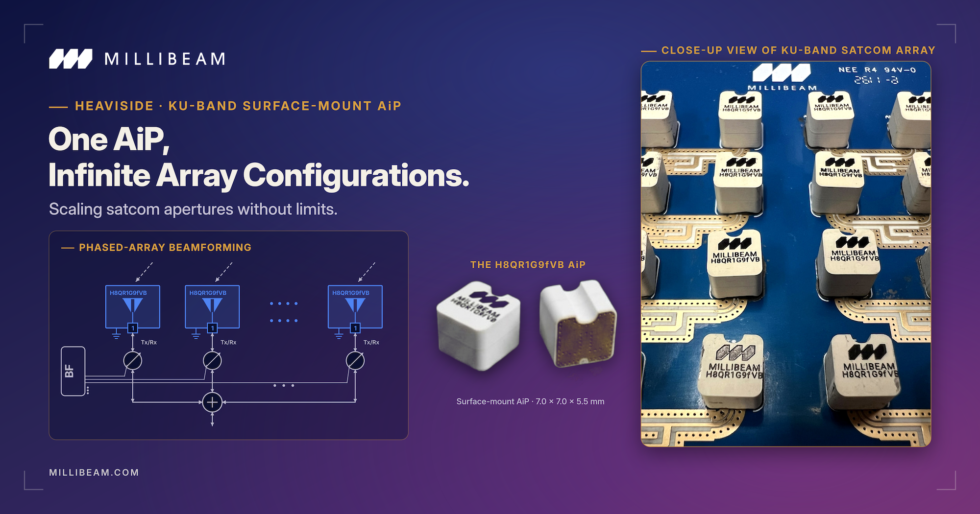
Scalable Ku-band SATCOM is a phased-array problem, and the antenna is usually where array designs run into trouble first. As terminals move from a single aperture toward arrays of hundreds or thousands of elements, the PCB-embedded antenna becomes a bottleneck: it ties the radiating element to one board stack-up, consumes routing space, and has to be re-tuned whenever the layout changes. The H8QR1G9fVB takes a different approach. It is a surface-mount antenna-in-package (AiP), built as a repeatable unit cell, that solders onto a standard PCB like any other component. The intent is simple to state and hard to execute: treat the antenna as a standard electronic component that is scalable, manufacturable and reusable.
⚙️ Performance at a glance
The H8QR1G9fVB operates dual-band across the Ku downlink (10.7 to 12.7 GHz) and uplink (14.0 to 14.5 GHz). Embedded antenna gain reaches up to 6.7 dBi on the downlink and 7.6 dBi on the uplink, with radiation efficiency above 90 percent and cross-polarisation discrimination above 20 dB. As a unit cell in a rectangular or triangular planar array it supports beam steering up to plus/minus 50 degrees, with mutual coupling between adjacent units kept low by design. The package measures 7.0 by 7.0 by 5.5 mm.
🔬 Why dual-band Ku in one package is hard
Ku transmit and receive sit in separated sub-bands. Holding radiation efficiency and gain flatness across both, in a single compact package, is the core antenna design problem. Most solutions optimise one band and tolerate the other, or split the function across two apertures, which defeats the point in a SWaP-bound array. The H8QR1G9fVB is designed from the outset for balanced performance across both bands, so a single aperture covers the full transmit and receive split without a separate antenna per band. In an array that balance has to hold not just in isolation but under the impedance environment created by neighbouring elements, which is why low inter-element coupling is treated as a first-order design target rather than an afterthought.
🔩 Reclaiming PCB real estate
In a dense array tile, space for beamformers, LNAs, PAs and routing is contested down to the square millimetre. At 7.0 by 7.0 by 5.5 mm the H8QR1G9fVB solders directly next to the active chain, which avoids long antenna routing, minimises interconnect and track losses, and frees board area for the rest of the front end. The radiating element stops competing with the electronics for the same copper.
🔬 Decoupled from the motherboard
The bigger structural win is that the antenna is decoupled from the board. A traditional embedded antenna is tuned to one stack-up, so any change to materials or thickness forces a redesign and re-qualification. The H8QR1G9fVB holds stable performance across a wide range of layouts: microstrip, stripline, CPW and CPWG feed lines, PCB thickness from 0.12 to 5.0 mm, and dielectric constant from 2.2 to 4.4. Because the antenna is encapsulated in a pre-qualified ceramic package, the motherboard can be designed purely around RF distribution, beamforming and thermal management. The result is simpler stack-ups, lower design risk, and a faster path from prototype to production.
📈 Built for volume and design-in
The part is placed by standard SMT automated pick-and-place, with manual placement supported for prototyping. It uses robust materials with high thermal capacity, tolerates placement misalignment up to plus/minus 0.25 mm in X and Y, survives a peak reflow temperature of 260 degrees C, and handles input power up to 25 W. These are the properties that decide whether an antenna can actually scale into a manufacturable array, rather than just perform on a single test board.
📡 Designing it into an array
As a unit cell the H8QR1G9fVB repeats across a planar lattice. Rectangular and triangular arrangements are both supported, and steering to plus/minus 50 degrees covers most fixed, mobile and on-the-move terminal requirements. Because each cell is identical and pre-qualified, array bring-up shifts from antenna tuning toward beamforming and calibration, which is where the design effort is better spent.
The H8QR1G9fVB is part of the MILLIBEAM HEAVISIDE portfolio. Simulation models and evaluation units are available. Request a datasheet or sample.
Designed in silicon. Proven in the field.
The parts discussed here are designed, characterised and shipped by MILLIBEAM. Browse the catalogue, filter by band and package, and request a datasheet.
