F1M1G1
5G NR Dual Connectivity Multi-band FR1 + FR2 RFIC (2Tx + 2Rx)

Engineered for demanding RF systems.
Built for integration.
Description
The F1M1G1 is a 2-channel sub-6 GHz and mmWave RFIC integrating frequency up-conversion and front-end functionality for 5G FR1/FR2 multi-band phased-array systems. Designed for macro base stations, small cells, fixed wireless access (FWA), and satellite non-terrestrial network (NTN) platforms, the device enables simultaneous FR1 and FR2 operation through a shared and resource-efficient RF architecture.
The F1M1G1 supports 5G FR1 and FR2 frequency bands with peak transmit power of 5 W and 0.5 W respectively, before the antenna. Its architecture enables high-EIRP beamforming systems while reducing reliance on large antenna arrays, high element counts, and calibration-intensive RF front ends, helping lower system power consumption, cost, and deployment complexity.
Features
- 5G FR2: 2Tx + 2Rx
- RFIN = 3.3 – 4.2 GHz
- RFOUT = 26.5 – 29.5 GHz
- Up-down conversion
- PA + LNA
- 5G FR1: PA + LNA
- RFIN = 3.3 – 4.2 GHz
- RFOUT = 3.3 – 4.2 GHz
- PA + LNA
- LO Section:
- LOin = 7.3 – 8.6 GHz
- LO = 22.8 – 25.2 GHz
- Frequency Multiplier (x3)
- LO Drive > 10dBm
- Isolated FR1 and FR2 paths
- Isolated Rx and Tx paths
- Supports carrier aggregation ~3.9 GHz BW
Applications
- 5G FR1/FR2: Small Cells, FWA
- 5G NTN: Satellite Constellations and Ground Terminals
- Defence Applications: Phased-arrays for Radar
System detail.

Functional block diagram
Configured as 2Tx + 2Rx for FR1 n78 and FR2 n257. Two receive inputs (RX1_IN, RX2_IN) accept 3.3 to 4.2 GHz or 26.5 to 29.5 GHz and are down-converted to the receive IF outputs (RX1_IF, RX2_IF) at 3.3 to 4.2 GHz. Two transmit IF inputs (TX1_IF, TX2_IF) at 3.3 to 4.2 GHz drive low-band outputs (TX1_LB, TX2_LB) at 3.3 to 4.2 GHz and up-converted high-band outputs (TX1_HB, TX2_HB) at 26.5 to 29.5 GHz. A 7.3 to 8.6 GHz LO input (LO_IN) feeds an on-chip x3 frequency multiplier for the mixers.
Ordering information
- F1M1G1: 5G NR Multi Band FR1 + FR2 RFIC
- F1M1G0: Bare Die Option
Source: F1M1G1 Datasheet V.0.0, page 1. Specifications and data can change without prior notice. The full datasheet is available on request.
 P1D1A15G NR 3.3 - 4.2 GHz 2Tx + 2Rx MIMO Transceiver
 H5D1E13.1-4.2 GHz, GaN MMIC General-purpose Amplifier in a Low-cost Package
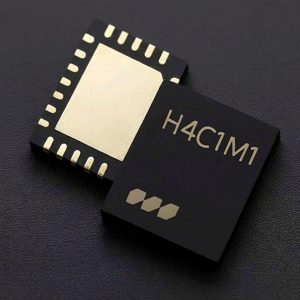 H4C1M13.3–3.8 GHz, 20 W Psat, 31 dB Gain, GaN Integrated Doherty Power Amplifier for 5G NR n78
Need the full datasheet?
Request the full datasheet, including electrical specifications, S-parameters and application guidance. Our engineering team will follow up, usually within one business day. Prefer email? Write to marketing@millibeam.com and quote the part number.
